Automatic Welding for CDU & Manifold Liquid‑Cooled Pipes: Weld Bead Appearance Is Not the Whole Story | In‑Depth Analysis by Mwelding at Shenzhen Summit
Mwelding Hosts Liquid‑Cooling Technical Session and Delivers Keynote Speech: Integrated Automatic Welding Solutions for Prefabricated Liquid‑Cooled Pipelines in Data Centers
Does a smooth‑looking weld bead on CDU stainless‑steel pipelines guarantee satisfactory penetration, sealing performance and internal pipe cleanliness? If an orbital welding machine covers the nominal pipe diameter of workpieces, does it mean the welding head can physically fit into densely‑packed manifold branch pipe gaps?
For liquid‑cooled pipe prefabrication factories and system integrators, real‑world challenges extend far beyond weld appearance. Critical concerns include adequate welding access, stable internal shielding gas protection, repeatability of parameters and positioning after product change‑overs, and whether mass‑produced welds can pass project‑specific inspection and acceptance criteria.
A visually appealing single weld is only the starting point. A qualified automatic‑welding solution must deliver consistently verifiable quality across welds of diverse structures and specifications.
On September 23, 2026, at the 6th Cloudsail AI Data Center Liquid‑Cooling Supply Chain Summit held at Shenzhen Yanzihu International Convention & Exhibition Center, representatives from Shanghai Mwelding Intelligent Welding Technology Co., Ltd. (Mwelding) chaired the morning session of Track 2 themed Development and Manufacturing of CDU and Core Liquid‑Cooling Components for Data Centers
, and presented a technical speech titled Integrated Automatic Welding Solutions for Prefabricated Liquid‑Cooled Pipelines in Data Centers
. As an original‑equipment manufacturer of orbital pipe welding machines, Mwelding shared a full‑scope engineering workflow covering working‑condition assessment, equipment selection, custom tooling design, process development and quality verification, tailored for different joint configurations of CDUs, manifolds and heat‑exchange equipment.
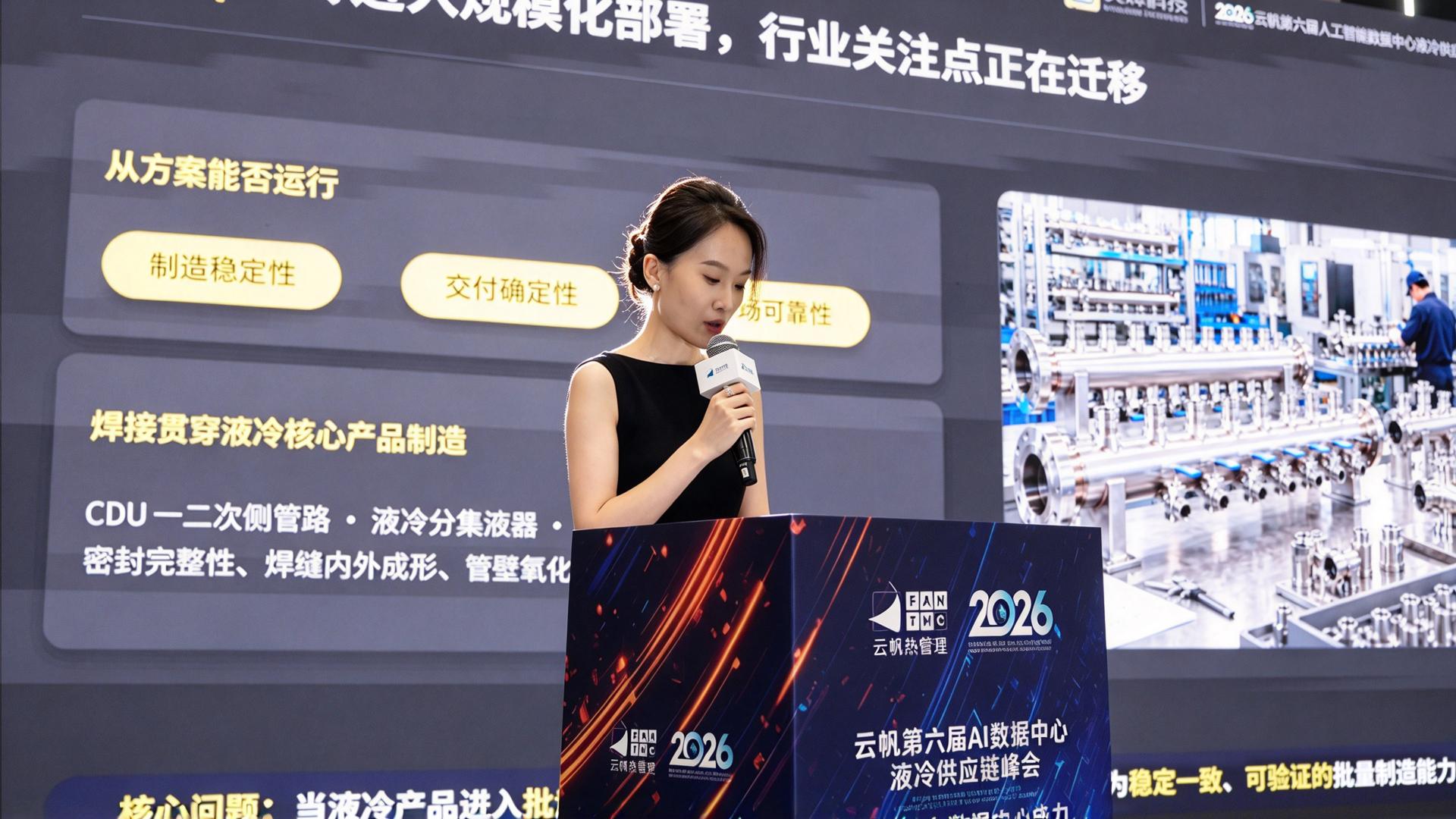
Figure: Mwelding delivers technical presentation at the 2026 Shenzhen Cloudsail Liquid‑Cooling Summit
01 | More Than Weld Bead Formation: Core Challenges for Liquid‑Cooled Pipe Prefabrication
Challenge 1: Welding Head Accessibility — Diameter Compatibility ≠ Practical Clamping Feasibility
Weld joints on CDU and manifold components are often surrounded by elbows, valves, adjacent branch pipes and support structures. Equipment selection requires evaluation of more than pipe diameter and wall thickness. Engineers must check welding‑head entry clearance, fixture closing space, straight‑section clamping length and torch travel clearance. For circumferential seam welding systems, additional checks cover stable workpiece positioning and rotation, torch angular posture and filler‑wire feeding space.
Challenge 2: Weld Quality — Look Beyond Visual Appearance; Verify Penetration and Internal Bead Profile
For thin‑wall stainless‑steel pipe welding, quality evaluation shall cover fusion and penetration, internal weld geometry, and high‑temperature oxidation conditions on inner pipe walls. Argon‑purge effectiveness inside pipes, shielding‑gas purity, flow rate, residual oxygen level and shielding duration all directly affect internal welding results. For liquid‑cooled pipelines with strict cleanliness requirements, borescope inspection and equivalent testing are mandatory. Acceptable external appearance cannot replace verification of internal weld conditions.
Challenge 3: Batch Consistency — Passing Trial Welds Does Not Eliminate Post‑Change‑Over Validation
Liquid‑cooling production lines frequently handle mixed pipe diameters, wall thicknesses and joint geometries. Weld outcomes are sensitive to fit‑up gaps, misalignment, material batch variations, fixture reference drift and heat accumulation during continuous welding. Programmable controls mitigate human‑operator errors. Nevertheless, recalled validated parameters, positioning restoration after specification switching, and stability of sequential welds must be validated under actual production conditions.
Weld formation, spatial compatibility, internal gas shielding, parameter repeatability and quality acceptance should be addressed within one unified process chain, instead of being treated as separate post‑weld remedial tasks.
02 | How to Select Automatic‑Welding Equipment for Distinct Weld Joints on CDUs, Manifolds and Heat Exchangers
Mwelding deploys its MWF, MWG, MWHF, MWH and MWP automatic‑welding series for various weld joints of core liquid‑cooling components. Equipment selection is determined by real‑world welding position, joint configuration, wall thickness, clamping conditions and acceptance specifications, rather than forcing one single machine to handle all application scenarios.
Thin‑Wall Stainless‑Steel Tube‑to‑Tube Butt Joints: MWF Series Closed‑Chamber Orbital Tube Welders
For CDU pipeline butt joints and manifold branch pipe connections with sufficient clamping clearance, the MWF series establishes precise positioning references via specification‑matched fixtures. Welding current, circumferential travel and arc start‑stop sequences are programmatically controlled. With proper internal argon back‑purge, the system prioritizes internal‑bead quality and inner‑wall oxidation mitigation while improving process repeatability for identical welds. Actual penetration performance shall be verified through trial welding according to material grade, wall thickness and joint details.
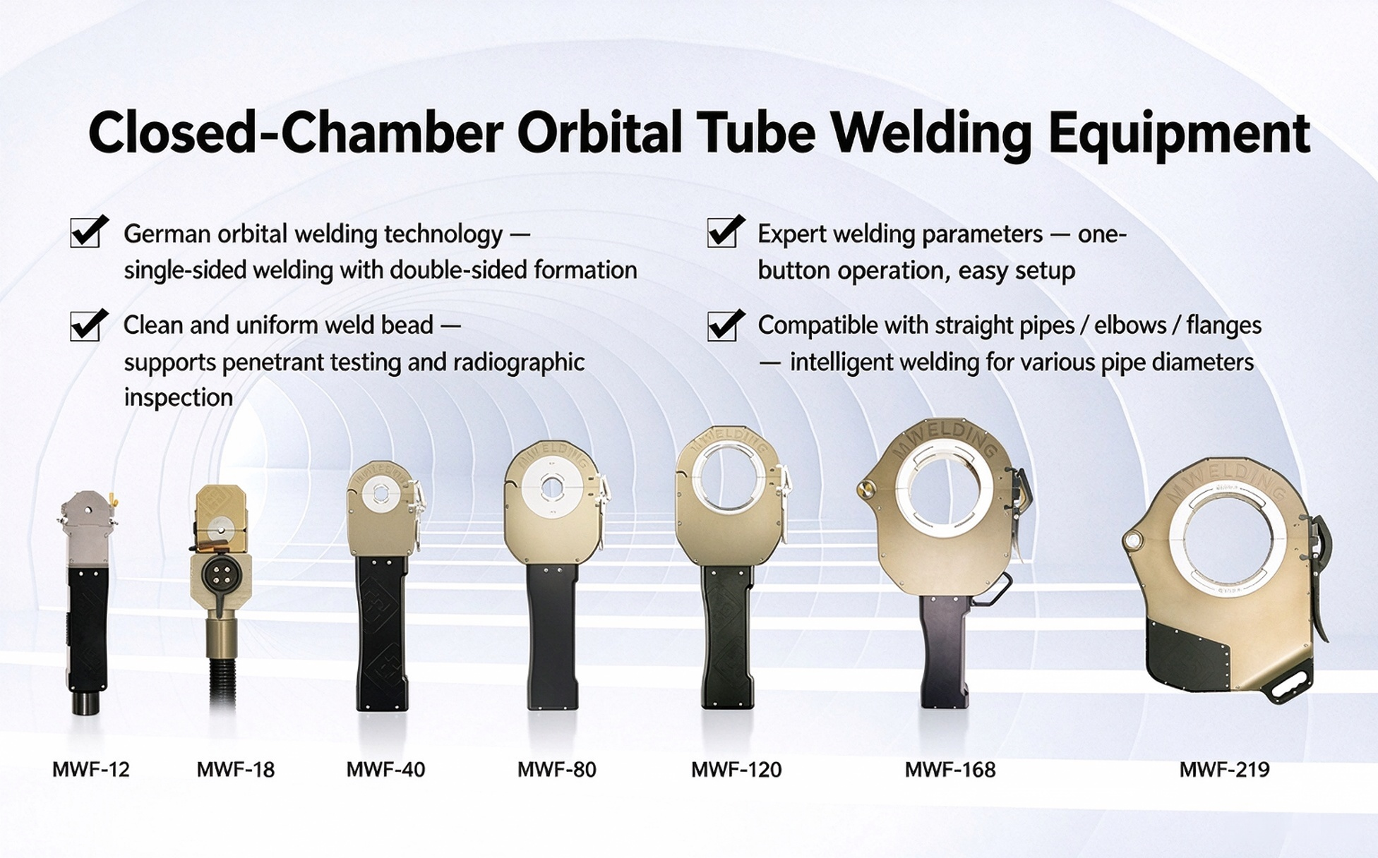
The MWF series is compatible with the MWA‑200 welding power source. This power unit stores up to 990 pre‑configured welding parameter sets for quick recall in repeated production. It can also auto‑generate initial recommended parameters based on input pipe diameter and wall thickness for further process validation. Parameter recall and auto‑parameter generation are separate functions. Parameter storage shall not be confused with full‑process data logging or quality traceability systems.
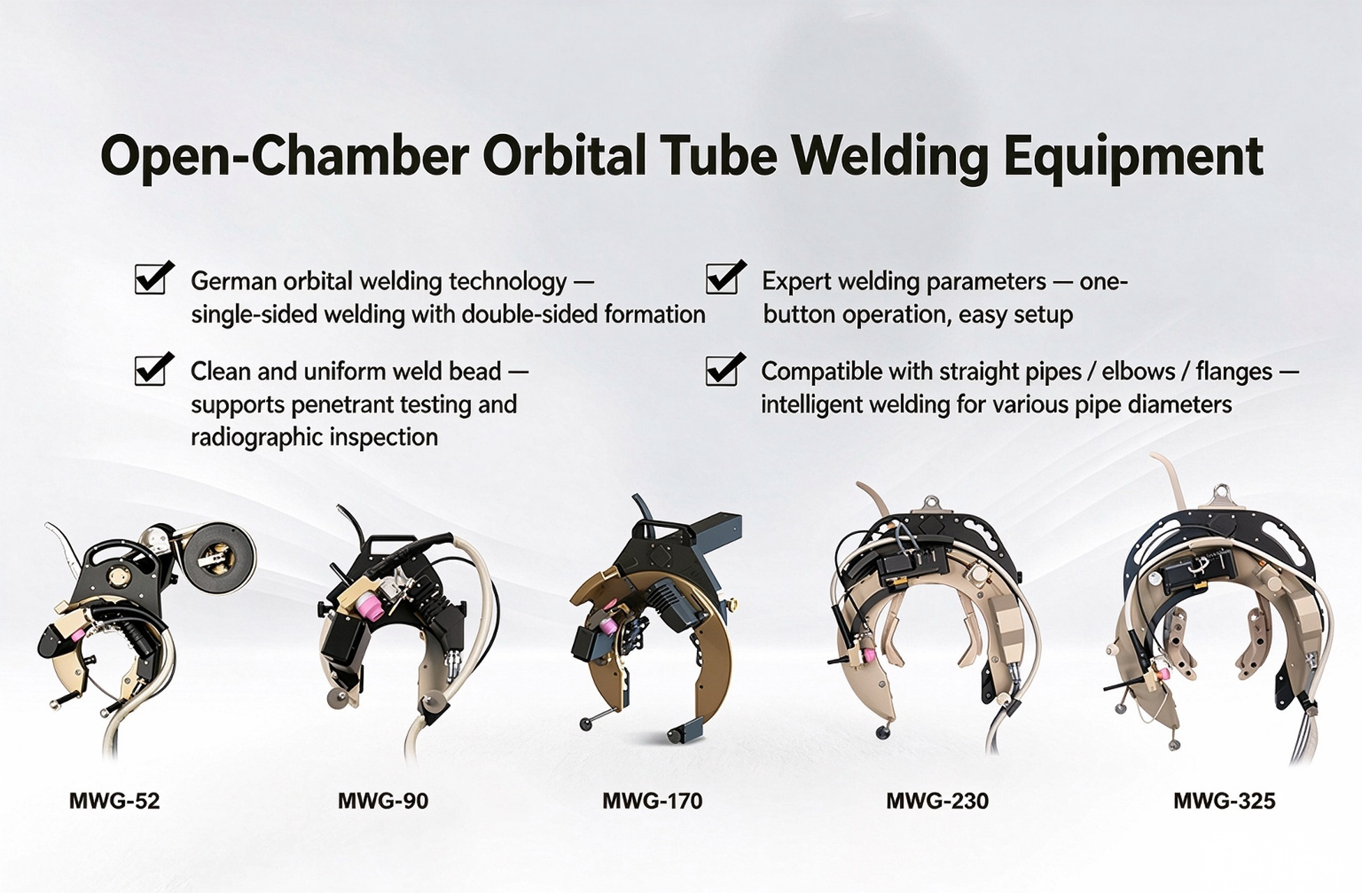
Space‑Constrained Installations & Special‑Profile Workpieces: MWG Series Open‑Chamber and Custom‑Built Welding Systems
Where closed‑chamber welding heads suffer spatial interference, or joints require filler‑wire procedures for specific groove geometries and wall thicknesses, open‑chamber orbital welding is recommended. For non‑circular profiles such as elliptical tubes used in heat exchangers, Mwelding has developed the custom‑purpose MWG‑90DA welding unit. Custom tooling, motion trajectories and welding programs work in tandem to achieve process adaption for special cross‑sections. The elliptical‑tube solution is application‑specific for heat‑exchange equipment and is not a universal replacement for thin‑wall circular‑tube butt welding on CDUs.
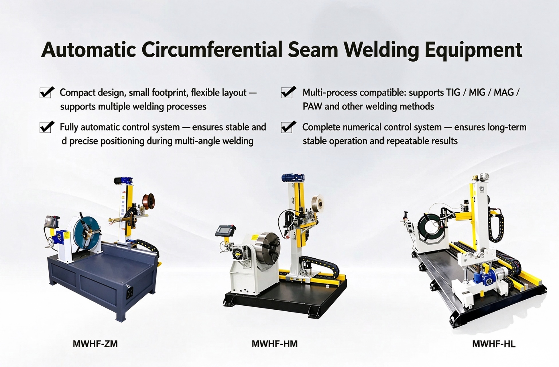
Circumferential Seams for Manifold Main Pipes, Housings and Flanges: MWHF Series Circumferential Welding Systems
For rotatable manifold main pipes, housings, nozzles and tube‑to‑flange connections, the MWHF series works with dedicated tooling, controlled workpiece rotation, adjustable torch posture and application‑specific welding programs to process butt circumferential seams and selected fillet welds. For fillet welds, inspectors must verify fusion performance, weld leg dimension and uniform circumferential bead profile. For thick‑wall or filler‑wire‑enabled joints, engineers shall validate wire‑feeding performance and heat‑input parameters.
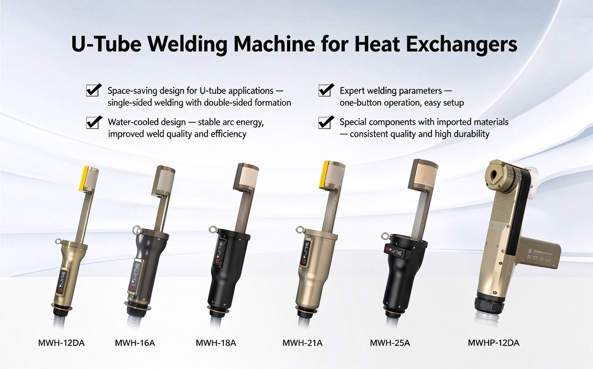
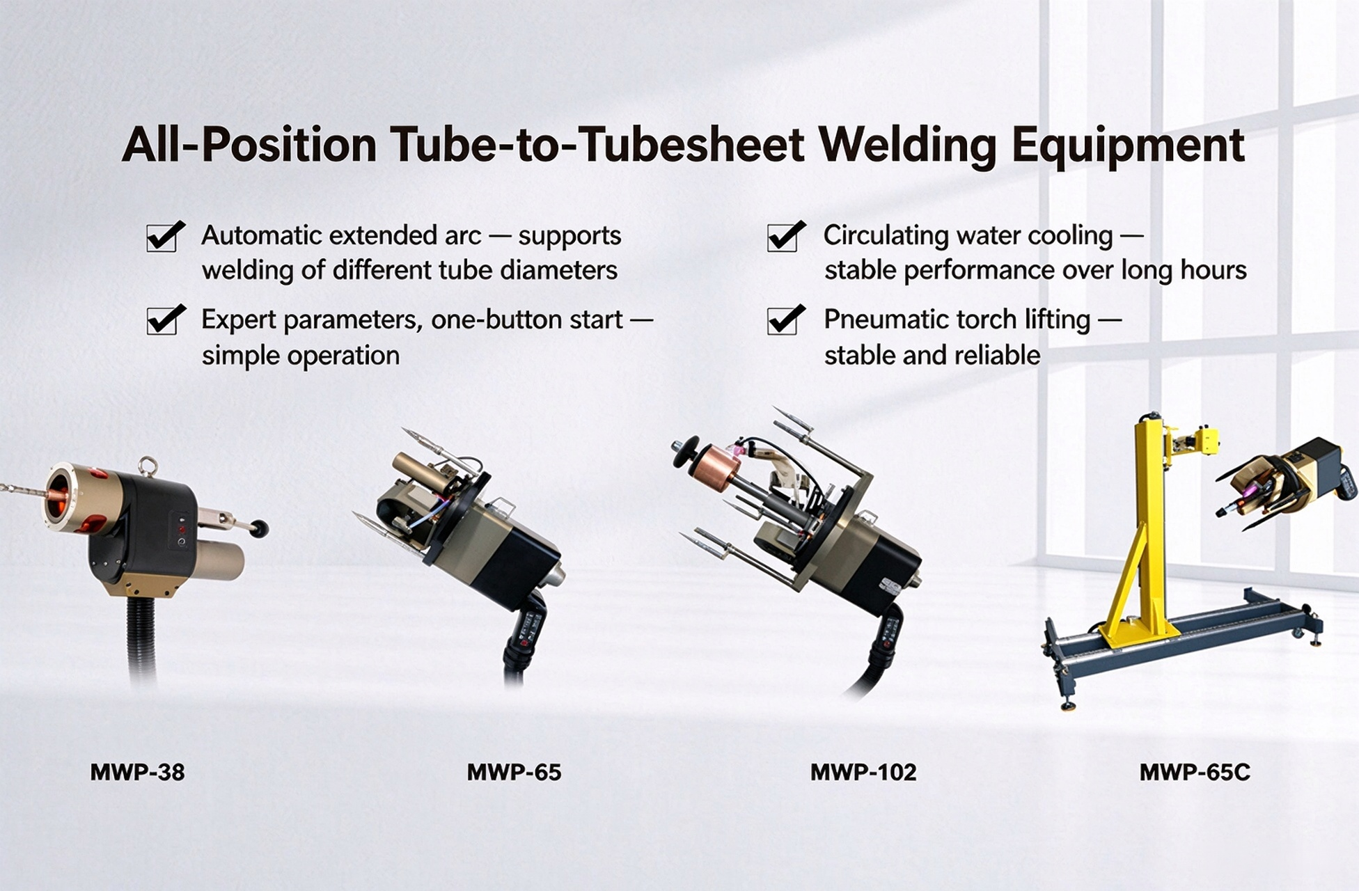
Heat‑Exchanger U‑Tube and Tube‑to‑Tube‑Sheet Joints: MWH and MWP Dedicated Automatic Welders
U‑tube welds in heat‑exchanger assemblies face challenges including limited tube pitch, bend radius, adjacent‑joint interference and cumulative heat input during continuous production. Tube‑to‑tube‑sheet joints impose strict requirements for hole alignment, torch centering and uniform circumferential bead formation. Mwelding applies the MWH series for U‑tube welding and the MWP series for all‑position tube‑sheet welding respectively. The two machine platforms are not directly interchangeable.
Target Welding Object for Liquid‑Cooled Pipe Prefabrication | Key Pre‑Selection Verification Items | Recommended Mwelding Solutions |
CDU / Manifold thin‑wall butt joints | Clamping length, torch‑closing clearance, internal gas shielding | MWF Closed‑Chamber Orbital Tube‑to‑Tube Welder |
Space‑restricted positions / elliptical‑tube and non‑circular components | Torch trajectory, fixture design, filler‑wire requirements, torch accessibility | MWG Open‑Chamber Orbital Welder / Custom‑Engineered Equipment |
Circumferential seams on manifold main pipes, housings and flanges | Rotational positioning, joint configuration, wall thickness | MWHF Circumferential Seam Welding System |
Heat‑exchanger U‑tube / tube‑to‑tube‑sheet joints | Tube‑to‑tube interference, heat accumulation / centering precision | MWH U‑Tube Welder / MWP Tube‑Sheet Automatic Welder |
03 | Delivering Practical Automatic‑Welding Solutions for Real‑World Operating Conditions
Customers require more than equipment model numbers. Core expectations include unobstructed torch access to weld stations, joints compliant with technical specifications, and stable mass‑production performance after specification change‑overs. Mwelding delivers tailored solutions through three pillars: in‑house equipment R&D, custom development for special geometries and field‑proven project validation.
Multi‑Series In‑House Developed Equipment to Support Application‑Driven Selection
Shanghai Mwelding Intelligent Welding Technology Co., Ltd. designs and manufactures the full‑range product portfolio: MWF closed‑chamber orbital tube welders, MWG open‑chamber orbital welding systems, MWHF circumferential seam welders, MWH U‑tube welders and MWP all‑position tube‑sheet welders. Each platform differs in clamping mechanism, welding kinematics, joint compatibility and process configuration. Solutions are assembled to match actual CDU, manifold and heat‑exchanger workpieces, instead of forcing all weld types onto one single welding setup.
Custom R&D for Special Structures: Synchronized Development for Tooling, Motion Trajectories and Welding Processes
Elliptical‑tube welding illustrates the complexity of non‑standard development. Changed workpiece cross‑sections require complete redesign of relative torch‑to‑workpiece positioning, motion‑path planning, clamping references and parameter matching. Mwelding developed the MWG‑90DA elliptical‑tube welding unit for heat‑exchange applications. Custom tooling, motion‑control logic and welding programs support either autogenous or filler‑wire welding workflows per joint requirements. This case highlights that integrated solutions demand tight coordination between machine hardware and welding processes.
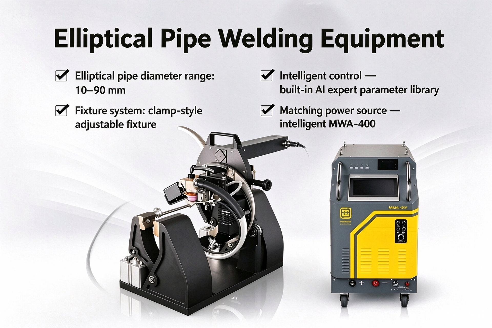
Figure: Mwelding MWG‑90DA elliptical tube automatic welding equipment
On‑Site Field Deployment and Validation to Ground Solution Design
Mwelding automatic‑welding equipment has been deployed for prefabrication and manufacturing of liquid‑cooling components in Guangdong‑based liquid‑cooling system integrator and pipe‑fabrication projects. Project execution covers weld‑joint review, clamping‑scheme design, process tuning and weld‑quality inspection. Equipment selection must evaluate both engineering drawings and physical test coupons.
In one liquid‑cooling‑equipment manufacturing project, Mwelding welding systems produced 304 and 316L stainless‑steel liquid‑cooled pipelines. Finished assemblies passed borescope inspection, helium leak testing, hydrostatic pressure testing and pressure‑cycle reliability validation. Hydrostatic test conditions reached 150 psig (approx. 1.03 MPa) with one‑hour hold time. Test results and acceptance criteria apply only to this specific project. End‑users shall follow their own internal specifications and acceptance documents for pressure‑bearing, sealing and cleanliness requirements.
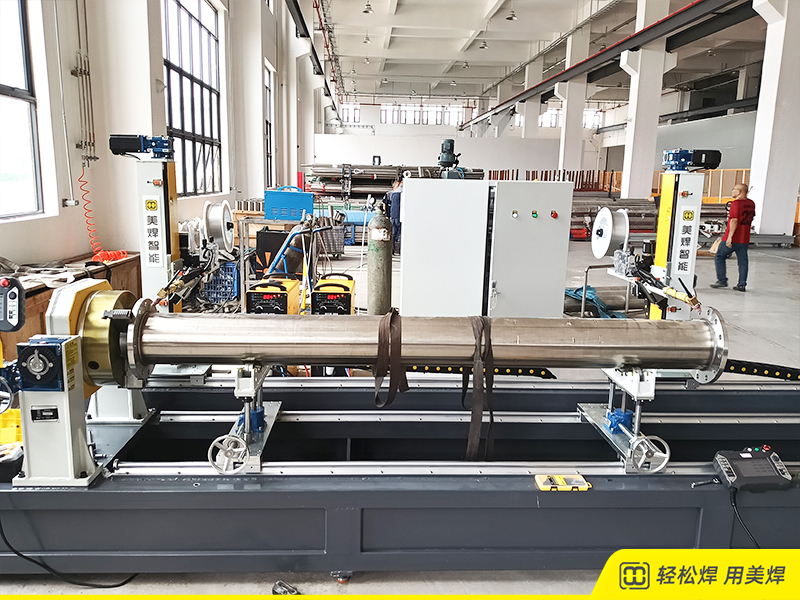
Figure: On‑site application of Mwelding automatic welding equipment for liquid‑cooled pipe manufacturing project in Guangdong
For Mwelding, multi‑series hardware constitutes the equipment foundation; custom engineering delivers application adaptability; physical‑part trial welding and inspection records serve as critical evidence to judge solution feasibility for each project. New materials, dimensions or joint designs from customers require re‑evaluation of equipment configuration and welding processes against real‑world operating conditions.
04 | Establishing Rigorous Weld‑Quality Validation Workflow: From Single Test Coupons to Continuous Prefabrication
Mwelding’s end‑to‑end solution deployment for liquid‑cooled pipe prefabrication defines clear process‑validation and delivery workflows beyond hardware procurement:
01 | Weld‑joint assessment: Collect material grade, pipe diameter & wall thickness, joint and groove geometry, fit‑up tolerance, weld‑joint location, surrounding structural features and acceptance criteria. Drawings and physical test samples shall be provided when necessary.
02 | Equipment and tooling definition: Validate torch entry clearance, fixture closing performance, workpiece positioning and rotation capacity. Confirm torch travel paths, filler‑wire requirements and shielding‑gas workflows.
03 | Trial welding and process validation: Test welding current, travel speed, arc start‑stop logic, filler‑wire feeding and internal shielding‑gas parameters for target joints. Inspect fusion, penetration, internal‑bead geometry and oxidation conditions.
04 | Change‑over and continuous‑operation validation: Evaluate weld repeatability after fixture replacement, program recall and positioning reset, as well as performance shifts caused by cumulative heat input. Define conditions requiring re‑validation.
05 | Project‑specific acceptance and hand‑over: Execute visual inspection, borescope examination, leak testing, pressure testing and required non‑destructive testing as per project specifications. Support on‑site commissioning and operator training. Where digital traceability is required, clarify data‑acquisition scope, record‑retention rules and system interfaces. Parameter‑storage functions shall not be mistaken for a complete traceability platform.
A genuine integrated solution delivers application‑specific hardware setups, process parameters, operational instructions and inspection benchmarks for physical workpieces — rather than merely completing one full automatic welding rotation.
05 | Four Critical Questions for Liquid‑Cooling Manufacturers Evaluating Orbital Pipe Welding Machines
For enterprises planning CDU, manifold or heat‑exchanger pipe prefabrication production lines or optimizing existing processes, these four questions support technical evaluation and supplier communication:
① Can the welding head physically access target weld locations? Share details of nearby elbows, valves, branch‑pipe spacing and straight‑pipe length. Avoid equipment selection based purely on nominal pipe diameter.
② What precise acceptance metrics apply to weld quality? Clarify requirements for fusion, penetration, internal‑bead geometry, inner‑wall oxidation, leak‑tightness, pressure resistance and mandatory inspections, instead of only focusing on external visual quality.
③ How are validated welding processes reproduced after specification change‑overs and continuous production runs? Confirm fixture‑swap workflows, program recall, positioning reset, shielding‑gas stability and re‑validation mechanisms. Do not overlook batch‑production risks just because trial coupons pass inspection.
④ What quality records must be retained? Distinguish between welding‑parameter storage, runtime production data, test reports and full digital traceability platforms. Confirm required configurations and system interfaces for your specific project.
Conclusion: Weld‑Bead Appearance Is Only the Starting Point — Every Weld Must Be Verifiable and Reproducible
At the 2026 Shenzhen Cloudsail Liquid‑Cooling Summit, Mwelding representatives chaired the morning session for Development and Manufacturing of CDU and Core Liquid‑Cooling Components for Data Centers
and delivered the technical presentation Integrated Automatic Welding Solutions for Prefabricated Liquid‑Cooled Pipelines in Data Centers
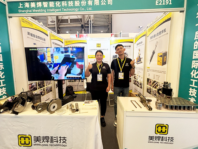
. Concurrent with the conference, Mwelding showcased automatic‑welding hardware for thin‑wall liquid‑cooled pipes at its exhibition booth.
For manufacturers engaged in CDU / manifold / heat‑exchanger fabrication, production‑line planning for pipe prefabrication or existing‑process optimization, Mwelding offers equipment selection consulting, custom‑tooling and non‑standard‑equipment development, welding‑process adaptation, pre‑sales trial‑weld services and on‑site technical support. Solution compliance with project requirements shall be judged by validation results and acceptance standards under actual working conditions.
The value of automatic welding for liquid‑cooled pipelines extends far beyond cosmetic weld appearance. Only by embedding welding‑head accessibility, fusion‑penetration performance, internal‑bead geometry, inner‑wall oxidation control, process reproducibility and quality acceptance into the initial solution design can equipment reliably support stable pipe‑prefabrication manufacturing.
Mwelding | Shanghai Mwelding Intelligent Welding Technology Co., Ltd.
Business Scope: R&D and manufacturing of orbital pipe welding machines; custom‑built automatic‑welding equipment and tooling development; welding‑process adaptation; integrated automatic‑welding solutions for liquid‑cooled pipe prefabrication.